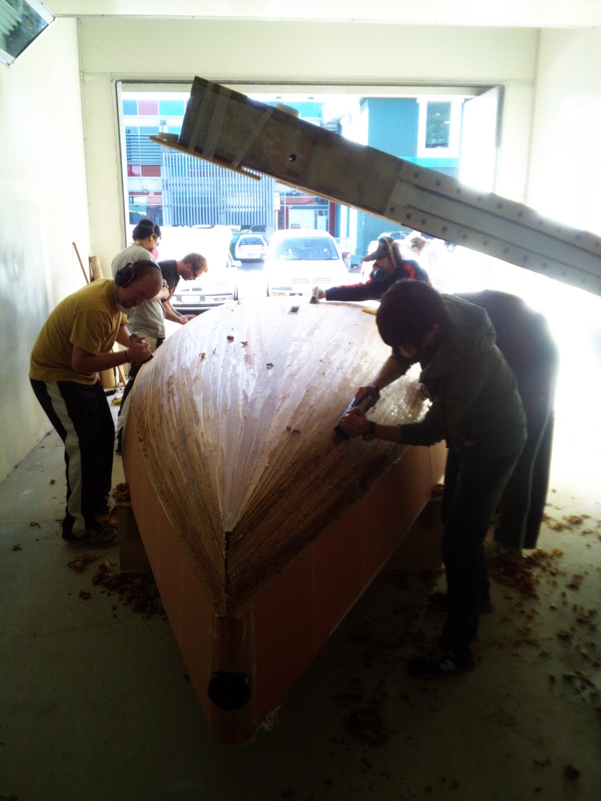
Once the deck/hull joint cured we were able to go ahead and flip the boat. We got about 14 guys, which was probably too many, and picked it up off of the temporary frames and rolled it over onto the splashes that we made. I have a video of this but it was nearly 15 minutes long and so I had to edit it and change the file type for YouTube. I was able to find a program that would do it for free, but it had to put in its own watermark.
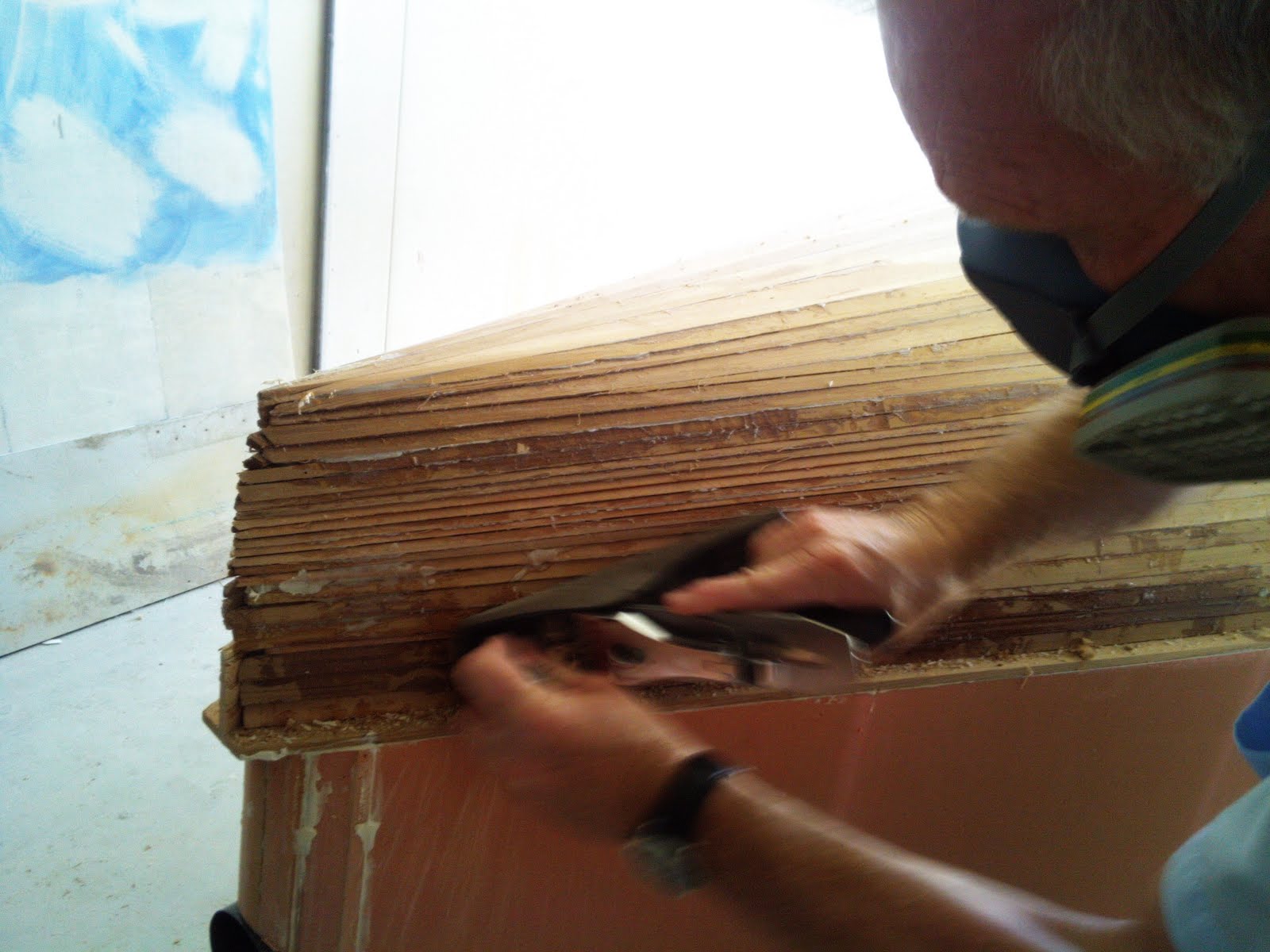
After the boat was turned over we spent nearly two days planing and sanding in order to get it fair. We did not use the pneumatic sanders in favor of the long boards. This required a whole lot more work on our part but this kept us from easily over sanding any single area. The temporary frames on the centercase was removed. We also figured out where the laps in the glass cloth would be and rebated back the wood. In order to get the boat fair there are a couple of things that you do. Technique in how you hold the plane and longboard are crucial but more than that you really need to take your time and feel the boat. As I would sand, I would pause every so often and feel the area starting inboard and working out and forward and aft. The high spots that still exist stand out fairly prevalently. We just tried to make sure that we did this (it was actually hard to communicate this to everyone because it seemed that some people really just wanted to sand or plane like mad). After we got the boat to what we thought was fair we dusted it off and then got a fair batten and ran it all the parts of the boat to see if there were still any bumps or hollows. In figuring out the glass cloth laps we actually cut the cloth and then laid in down on the boat, marked the area and then sanded to ensure we had it correct. We really wanted to make sure that the laps did not stick up because if it had to be sanded down that would negate the entire purpose of the laps. If the the high in the lap needed to be fixed when it is being painted then that can also take an extraordinary amount of time. We then vacuumed the enitre hull and proceeded to fill whatever gaps that exist with filler so that no air can be trapped inside the the boat is glassed.
During the final stages of sanding we also started installing the chain plate in the topside. This is 8 mm thick glass plate that goes from the sheer to the chine and is about 100 mm tapering to 40 mm wide. This is for the shrouds. When the boat is rigged it is going to having a fore-stay and two shrouds that are raked aft and no backstay. We installed this plate in nearly the exact same fashion and we did for the plate on the transom, router, chisel, sand paper. In order to get them from sliding around while the epoxy was drying we got two lengths of wood and screwed them over the plate and then used a third length and wedged it in from the floor. Once the plate set, we sanded back the thickness of another piece of glass about 40mm wide. The extra piece of glass ensures that there is a good stick between the plate and the final laminate sits fair.
The next step is applying a sealer coat to the wood. We did not have enough of the actual sealer so instead we just used the same room temperature cure epoxy (WEST system) that we have been using for the majority of this build. Wood has a natural wicking tendency and so if we did not seal in and put the glass and resin down then the resin that should be in the glass would get soaked up into the wood, thus ruining our fiberglass job.
The next step is actually putting the glass down. This laminate, EDB400, requires extra special care because it is on the outside and we are using the room temperature cure epoxy. When the owner goes to have this boat painted it needs to look perfect, for him and his pride but also for us. So when we lay down the glass and pay attention to the laps and folding the glass over onto the deck (for structural integrity and stiffness) we need to be very careful. We decided to do this part of the job in two different sections, in order to reduce the difficulty factor. We also went through all of the steps of vacuuming. The main thing that I would like to mention here is about how the glass is folded onto the deck.
While we were putting on the resin we made sure that we had extra sheets of cardboard down so that if resin was dripped down onto the floor it would get on the card and we could just remove it and stay clean. So when we got the glass and resin down properly from the center line working outboard and then down the topside it was time to get the 50 mm around and onto the deck. This was done both with brushes and squeegees, but there were some ways to utilize these two tools. When we used the brush and soaked the glass with the brush and kind of stuck it to the deck. Then we would go back over with the squeegee and get a really fit. If we worked the other way around we had difficulties. The brush tended to dripped resin down onto your hand and glove and with the squeegee we were simply not able to get the resin onto the job.
Just before we took the deck off of the frames we got underneath and put some marks onto the foam where the deckline is so that when we took the deck off of the temporary frames we know where to cut it off (remember when we made the deck temporary frames we made them 50mm bigger so that we would have an area to apply the vacuum tape). Once we flipp the deck over we took a jig saw and cut down that line that we drew on using a fair batten. We changed the angle on the jigsaw from a large bevel aft tapering to nearly plumb forward near the bow to allow for the shape of the topsides on the hull to fit as nicely as possible. Unfortunately, we had to put the deck on and take it off several more times than we would have wanted due to slight overages in the deck foam, but ideally, we should be able to get that line and then trim it off in one go. Another issue that arose when we were attaching the deck was the centercase. We have already installed in to the hull but had not yet cut out a spot on the hull. It is actually quite a tricky cut as well because the forward face of the centercase is plumb the the aft face is raked aft. We trimmed the hole on the deck slightly larger on the aft side while having it nearly dead on forward (allowing for epoxy of course). Once we had determined that the deck and hull fit together nicely we made up the resins. On the flanges that we built on the girder, transom and topside we put down ample epoxy in order to properly squash bond the deck and hull together. On the station 11 and collision bulkheads we actually used a nail that we bent at a right angle and installed it into a power drill. This allowed us to easily router out the foam while the leaving the fiberglass that had already hardened. We then filled the gap in with enough rubberized epoxy (strong resin that bonds fiberglass to fiberglass extremely well, no need to glass tape the joint).
Now I will explain what all of these photos and videos are and what we had to do to the underside of the deck in order to be able to attach the the two havles.
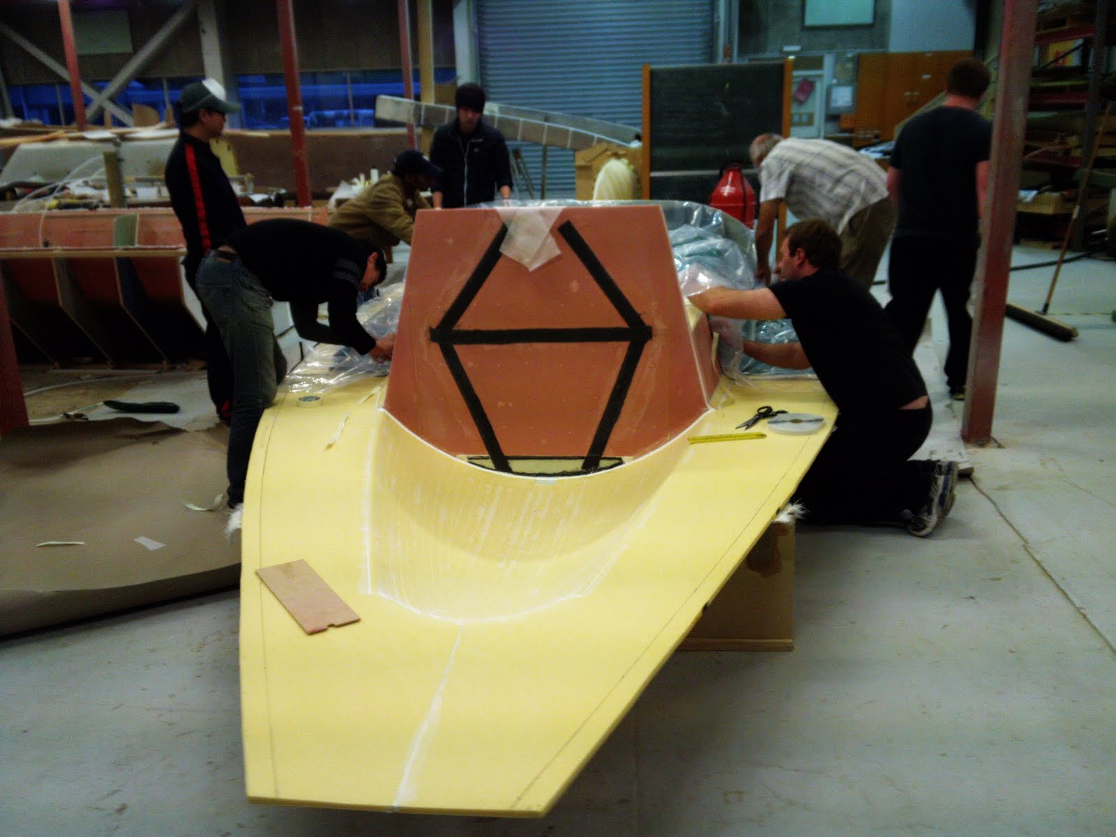
On the transom we needed to attach some glass plate for where the twin rudders and an outboard engine will attach. If we were to just attach the rudders and outboard (well, we would not be able to attach the outboard) to the foam the chance of them just breaking right off is extremely high. This glass plate needed to be glued right to the fiberglass that we already put on. We had to router out the foam in the area that everything goes and then chiseled and used a hack saw blade to do the rest.
The next series of photos deal with the bulkhead that was installed on the deck. The designer had initially want to have the bulkhead touch all sides so that you would not be able to get in around it and also had designed it to be 10 mm thick. Once we flipped the deck over he decided that it needed to be closer to 16 mm thick and instead of touching the port and starboard sides just take it the width of the cockpit sides. Naturally, now, we had quite of bit of shaping in order to get this all done how he wanted. In addition to these new designs, we had to still extend the bulkhead to the hull and shape it because when the temporary frames were designed and constructed we did not plan on building the bulkhead directly in the deck. So we got a piece of foam and thickness-ed it down to 6 mm on the wide belt sander and then attached little triangle pieces on either side to fill in the gaps. We then coated it in expoy and vacuumed the new pieces to the old bulkhead. Next, just as we had done on the outside of the deck, we had to install carbon uni strips that will disperse the weight of the mast down to the hull. We did not need to rebate in the carbon uni like we did last time because this is all on the inside of the boat. We then calcualted out the correct distance the bulkhead needs to extend to touch the floor on the hull and cut out that shape.
After we had finished with the glass plate installation and all the work on the bulkhead we were able to glass and vacuum the deck. The glass was the EDB240 because it is on the inside of the boat, therefore does not need to be as stiff, therefore saving weight because there are fewer glass fibers.
The centercase is the hole in the boat where the centerboard and keel go through. This gives the boat lateral resistance as well as a type of anchor or pivot point against the wind when sailing. This was made by wrapping several layers of fiberglass around a wooden jig that was made. We then had to cut holes in both the deck and the hull that would fit it. we decided that it would be considerably easier to attach the centercase to the hull first and then after the deck was finished and flipped we would then attach the centercase to the deck after we had it in place and attached it to the hull. We attached the centercase to the hull by finding the correct vertical height as well as centering it in the boat and making sure it was plumb as well, then cove and glass. We doubled the strips of glass and staggered them by 20mm to make it stronger because clovegro told us on several occassions that there is nothing worse than trying to fix a broken centercase. It was glass into the hull and the forward part of the girder. It is aft of the station 7 bulkhead by 150 mm or something so the extra part of the girder that we cut off is going to be installed between the centercase and the bulkhead for additional support. Later we are going to attach some cones to the outside of the centercase which is for the rig that will raise up and down the centerboard because this is a trailer-able boat.
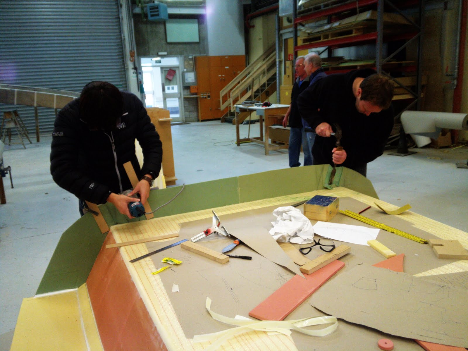
So if you can remember back to the hull of the boat, or simply have a working finger that can scroll down, you will notice that the shape of the boat is there but there is no structural support. This is where floors, girders and bulkheads play a part. A bulkhead is fancy boat talk for a wall (going athwart and girder is going fore/aft). A floor is just a bit of foam laminated athwartship that gives stiffness without blocking passage, essentially. This boat has three bulkheads, two girders and five floors (technically two or three are nearly called rings but they are basically the same thing only differing in how high they go onto the topsides or deck).
Two of the bulkheads were traced out using a very scientific device called a baked bean stick by clovegro, although I seriously doubt that that is what they are called out in the industry. Ours was a simple piece of plastic that was about 600 mm long, 60 mm wide and tapering. It has notches cut out like teeth on a saw but only like four of them and they are big. It would be a lot easier to just put in a photo but I never took one and can not find the stick so I can only describe it. We cramped in a large piece wood or mdf and then put the stick on the hull and traced the shape onto the mdf. If this is done over and over following the shape of the hull you can then take the piece of mdf over and redraw it on cardboard and then you will have the shape the the bulkhead needs to be cut to. Simple enough, right? These two bulkheads prelaminated and then attached to the boat before the deck while the other one has already been discussed because we built that into the deck.
The main girder was lofted onto card board using the infomation from the autoCAD drawing and then cut and laminated. This girder was prelaminated as well and then attached. This girder was the one that would have the weight of the cockpit sole on it and would also intersect with the station 11 bulkhead creating a t-frame beam for more support, and run from the centercase to the transom. Another girder which is built just like the floors is up forward near the collision bulkhead and ties together the three ring floors.
The floors were made using strip of foam that were about 8 mm think and 40 mm wide and the butting them together to go the width of the boat. We hot glued them into place and then ran some carbon uni strips and then coved and fiberglass cloth-ed them into place. Once they are hardened they are nearly impossible to bend and create a great stiffening support without adding to much weight or reducing cabin space.
The last bit of trickiness is the flange. Because the station 11 bulkhead is, in fact, there we are unable to get inside the boat to cove and glass the deck in place once we drop it on. So we built these flanges that can be squash bonded down onto. the flanges were created by measuring the deck camber (curve of the deck) and the thickess of the deck and then attaching some mdf to the inside of the hull with some plastic tape (packaging) to the underside. The we attached some peel-ply and cove and then used the fiberglass tape to make them. After the resin set we were then able to remove the temp frames and we had the flanges. This was also done for the transom.


