Thursday, May 26, 2011

Strip Planking


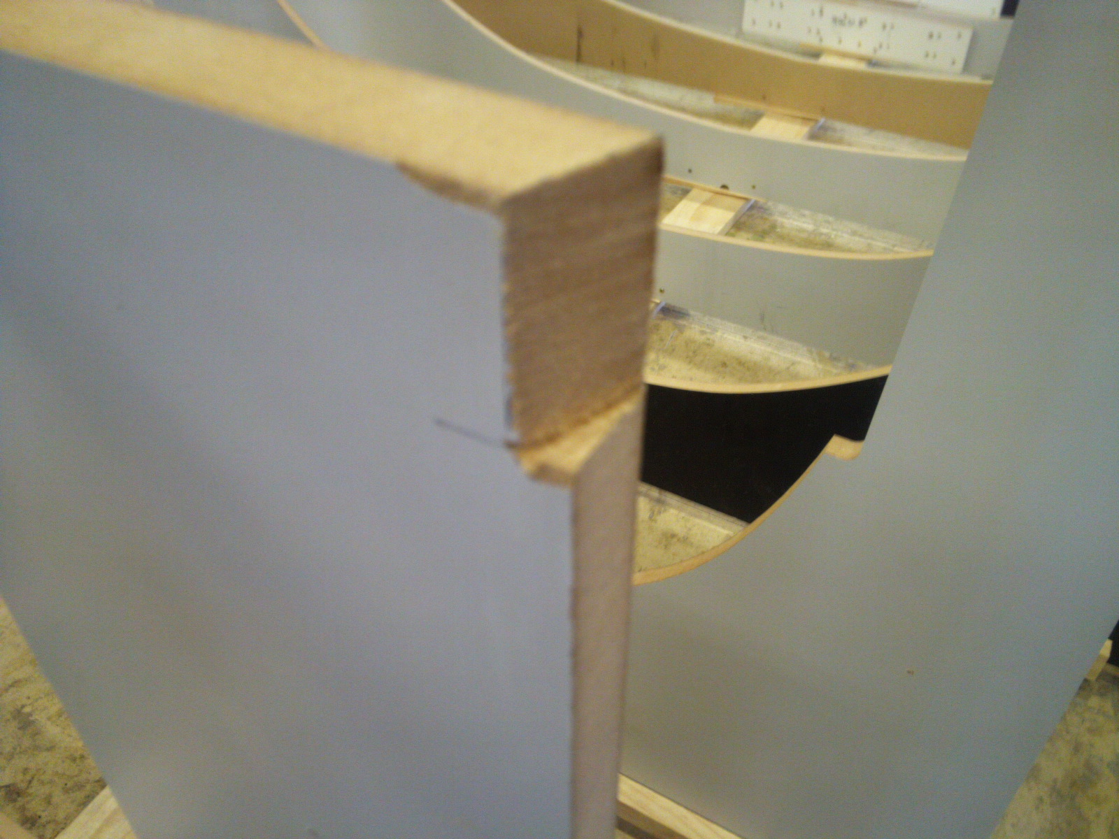
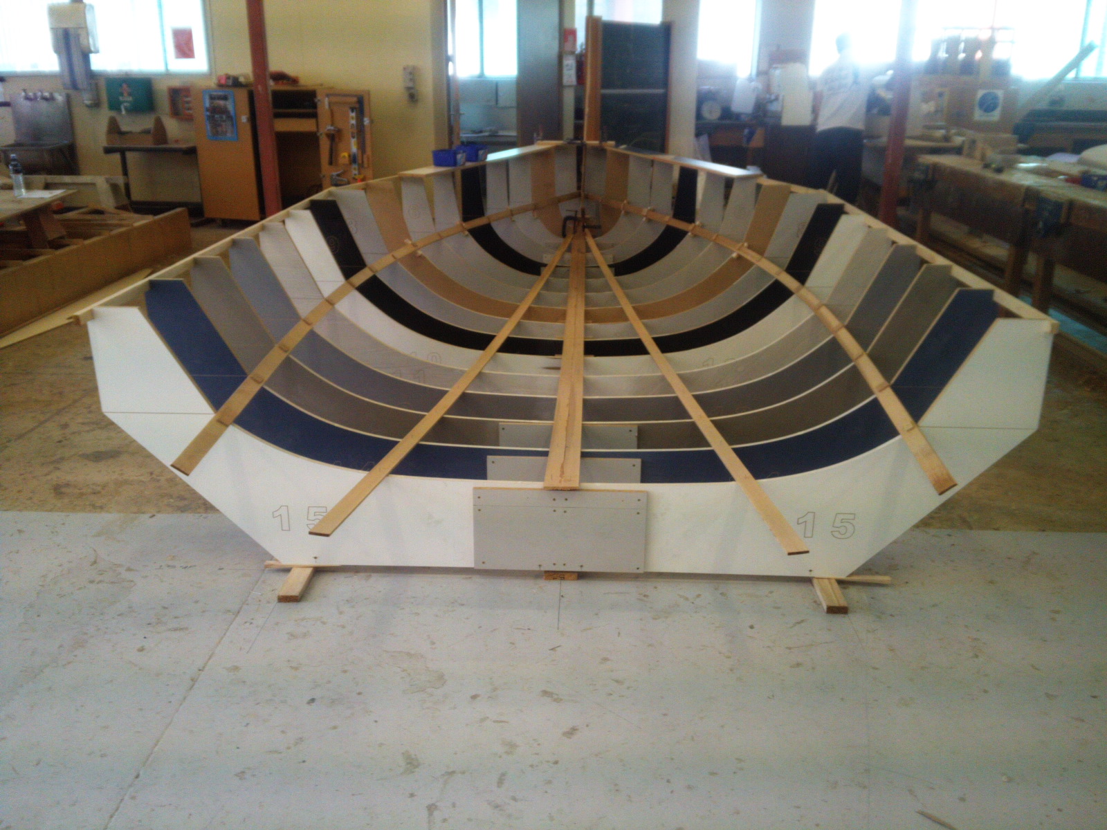
This post covers a lot of aspects of strip planking in just a couple photos and it was nearly 2 whole weeks of work if I am not mistaken.  I will try to recount the steps and problems that occured with strip planking as I best I can.  The first thing that we did was get two planks down that had their join right down the centerline.  These planks had to be tapered and beveled because of the very small area that we have at the bow of the boat but the need to fit as many planks as we can so they nearly go to a point.  We added an extra mdf frame between the 0 and 1 frames that ran fore-aft so that we had something a little bit more substantial to stabilized the smaller planks.  On the 0 zero frame, most forward, we attached wood blocks just around the smallest opening so that the planks that cant fit into the small hole can rest of the blocks.  I can not really explain nor would photos show how incredibly tight the fit was and how hard and long it took but I personally was able to fit the planks.  Fitting the planks on the rest of the boat were quite simpler other than the chine plank. The main problem here was that there was so much twist in the shape of the boat aft to forward that the plank nearly could not bend that way.  The way that we were able to fix the problem was to run a saw blade down the plank twice.  So we split the plank at the forward end into thirds and ran the cut back halfway and two-thirds of the way down the plank.  this allowed the individual pieces of the plank to twist easier.  This twist is commonly known as edge set.  Edge set is a problem because once we would take off the fasteners the plank would just pop back into its normal shape which could break glue bonds or cause the boat to be unfair.  After we had a couple of reference planks we were able to just lay other planks into place taper then how they needed to be, this was a very smooth quick process.  We used nails to hold the planks in place and then just back filled the planks after they had all cured and were installed.


Final Stabilization


These photos represent our discussing and solving the problem of how to permanently support the boat so that whatever leaning or weight that is applied to the boat it won't just fall apart.  We cut the frames back at the top to fit a thin plank that runs the distance forward to aft so each frame is supported against the others.  Then as the drawing depicts, we ran another plank from the 10th frame down to the floor on a angle and glued and screwed in down.  Now we can start planking, walking and nailing on the frames without worrying that they could fall over.

Temporary Frames

The beam is slightly wider than they make mdf planks so we had to attach halved frames together.  We first had them cut on a CNC which is an automated machine ran by a computer which after it has been programmed will cut basically any shape.  After we attached the frame halves, ensuring they were square, we were able to start setting up the frames onto the building base.  The photo with all of the levels is quite interesting in that it shows most of the ways that we had to worry about the frames being set up: plumbness, in-winding, and the waterline.  We used a theodolite with some reference marks to set the remaining frames because it is considerably easier and more accurate.  Also we had to attach the frames to something steady because there would be nothing worse than doing all of this work and then having them all fall over like a stack of cards. 


The Grid


There were several things that we had to make sure that we did, most important of which was getting the centerline and forward and aft perpendicular completely square.  All of the future frames or bulkheads or floors that will be ultimately referenced back to these lines so they need to be perfect.  After we drew the lines on the concrete and attached planks using no more nails, we redrew the the centerline and attached blocks for the temporary frames that will support the structure.


Rob Shaw 5.5m

In March we started building a yacht designed by Rob Shaw, one of the teachers here.  It is 5.5m LOA with a 2.4m beam.  The boat has a fairly open cockpit which I really like.  It has a plumb bow and has a strip-planked 8mm thick western red cedar hull with the topside and deck made of foam with varying densities and thickness.  All of my future posts will be about the procedure, problems and answers in its construction.