Thursday, June 30, 2011

Centercase

The centercase is the hole in the boat where the centerboard and keel go through. This gives the boat lateral resistance as well as a type of anchor or pivot point against the wind when sailing. This was made by wrapping several layers of fiberglass around a wooden jig that was made. We then had to cut holes in both the deck and the hull that would fit it. we decided that it would be considerably easier to attach the centercase to the hull first and then after the deck was finished and flipped we would then attach the centercase to the deck after we had it in place and attached it to the hull. We attached the centercase to the hull by finding the correct vertical height as well as centering it in the boat and making sure it was plumb as well, then cove and glass. We doubled the strips of glass and staggered them by 20mm to make it stronger because clovegro told us on several occassions that there is nothing worse than trying to fix a broken centercase. It was glass into the hull and the forward part of the girder. It is aft of the station 7 bulkhead by 150 mm or something so the extra part of the girder that we cut off is going to be installed between the centercase and the bulkhead for additional support. Later we are going to attach some cones to the outside of the centercase which is for the rig that will raise up and down the centerboard because this is a trailer-able boat.


Floors and Bulkheads and Flanges

So if you can remember back to the hull of the boat, or simply have a working finger that can scroll down, you will notice that the shape of the boat is there but there is no structural support.  This is where floors, girders and bulkheads play a part.  A bulkhead is fancy boat talk for a wall (going athwart and girder is going fore/aft).  A floor is just a bit of foam laminated athwartship that gives stiffness without blocking passage, essentially.  This boat has three bulkheads, two girders and five floors (technically two or three are nearly called rings but they are basically the same thing only differing in how high they go onto the topsides or deck).  

Two of the bulkheads were traced out using a very scientific device called a baked bean stick by clovegro, although I seriously doubt that that is what they are called out in the industry.  Ours was a simple piece of plastic that was about 600 mm long, 60 mm wide and tapering.  It has notches cut out like teeth on a saw but only like four of them and they are big.  It would be a lot easier to just put in a photo but I never took one and can not find the stick so I can only describe it.  We cramped in a large piece wood or mdf and then put the stick on the hull and traced the shape onto the mdf.  If this is done over and over following the shape of the hull you can then take the piece of mdf over and redraw it on cardboard and then you will have the shape the the bulkhead needs to be cut to.  Simple enough, right?  These two bulkheads prelaminated and then attached to the boat before the deck while the other one has already been discussed because we built that into the deck.

The main girder was lofted onto card board using the infomation from the autoCAD drawing and then cut and laminated.  This girder was prelaminated as well and then attached.  This girder was the one that would have the weight of the cockpit sole on it and would also intersect with the station 11 bulkhead creating a t-frame beam for more support, and run from the centercase to the transom.  Another girder which is built just like the floors is up forward near the collision bulkhead and ties together the three ring floors.

The floors were made using strip of foam that were about 8 mm think and 40 mm wide and the butting them together to go the width of the boat.  We hot glued them into place and then ran some carbon uni strips and then coved and fiberglass cloth-ed them into place.  Once they are hardened they are nearly impossible to bend and create a great stiffening support without adding to much weight or reducing cabin space.

The last bit of trickiness is the flange.  Because the station 11 bulkhead is, in fact, there we are unable to get inside the boat to cove and glass the deck in place once we drop it on.  So we built these flanges that can be squash bonded down onto.  the flanges were created by measuring the deck camber (curve of the deck) and the thickess of the deck and then attaching some mdf to the inside of the hull with some plastic tape (packaging) to the underside.  The we attached some peel-ply and cove and then used the fiberglass tape to make them.  After the resin set we were then able to remove the temp frames and we had the flanges.  This was also done for the transom. 


Wednesday, June 22, 2011

The Stack of the Deck

Like I discussed earlier the glassing of the deck was considerably different from that of the hull.  For one, we used a different type of resin.  The hull was a room-temperature cured epoxy while we used APR and APH that used a 4:1 ratio by weight on the deck which requires the deck to be heated/cooked to fully allow the resin to harden.  One benefit of this is that the deck does get stiffer but also allows us to have a considerably longer pot-life.  We could work at our own pace in getting down the peel-ply and everything else needed to vacuum.  The second difference is the stack.  The stack is the different layers of glass peel-ply and so forth used before we could walk away and say finished job.  I will go through the layers one by one.  The glass was the first thing to go down.  The glass on the outside of the boat, not just the deck, is EDB400.  This means that the glass is a double bias with the direction of the fibers crossing at 45 degrees.  The 400 signifies the weight of the cloth in grams per square meter.  After the glass is the resin.  We typically do not record the resin in the stack but I like to because it removes doubt as to when the resin will be applied.  We tried to have a 50/50 ratio by weight of resin to glass.  The next layer is peel-ply.  This is so the glass takes on the feel and shape of the peel-ply as well as protecting the glass from contaminates until we need to paint or attach something else.  The glass and peel-ply need to be laid down and smooth out so that there are no wrinkles or air bubbles and ensuring that there is the right amount of resin.  The rest of the layers do not require such care.  Perforated plastic goes down next which allows the rest of the layers to comes up easily as well as a way for excess resin to escape from the glass and peel-ply.  Next is mesh.  It does not really matter what type just as long as it allows air to flow freely from every part of the bag to the vacuum.  (What would happen if one section of the vacuum sealed off before all of the air was removed?)  After this we put down the vacuum bag.  This is not so much a bag a a big piece of plastic that has no holes.  We line the edge of the foam with vacuum tape, similar to puddy but is extremely sticky.  We then go around and seal then edges of the bag on the tape.  This part is done pretty much how you want with no specific right or wrong but you need to make sure that you have plenty of bag and put in many 'darts' in order to eliminate all chances of spanning.  Darts should be put as you see fit.  We always tried to put in too many because too few could cause the vacuum to span and bend the foam out of shape or snap it all together.  We wrapped green mesh down into the vacuum hose as well and laid that over the other green mesh allowing for the hose to have plenty of bag around it so that it did not crease the foam underneath if it spanned.  After the vacuum is turned on we go around and listen for leaks or holes along the bag and try to fix it.  We had a gauge set up so we could see if we had a perfect seal or not. 

When we applied the resin to the aft part of the deck where the transom was we had to be extra careful.  if the resin ran down where the vacuum tape need to go then the tape would not stick and therefore possibly ruin the vacuum all together.  We applied tape to the edge in order to try to fix the problem before it happened but it did not work. We spent several hours after class was technically over trying to get a good vacuum seal but nothing was working.  we ended up needing to cut off a portion of the transom in order to get some type of a seal but it still was not perfect. 


Transom

We determined that the best way to attach the transom would be to attach it to the deck and then build up a flange on the hull and squash bond it.  However, this did require so amount of manipulation of the 15th frame that was already set up.  We would also glass down the transom when we glassed the rest of the outside of the deck and so we had to move the frame in by the thickness of the transom and glass and resin.  This part was fairly easy, but because it was now further forward we had to sand back the cockpit side part of the frame so that it would not change the shape.  We also had to figure out what the exact shape of the transom would be.  We could have just done some manipulations of the drawing on autoCAD and printed it out full scale on the large printer but clovegro wanted us to learn how to do things by hand because he 'reckons that you young dudes will forget and the stuff that has been passed on for generations will be lost.'  So what we did was trace the shape of the transom top from the temporary frame and then the bottom from the inside of the hull and simply measure down and connect the two drawings.  We also had to then make sure that the transom would not hit the floor.  We had not allowed for the transom to be attached to the deck and so we were still not sure if the frames were high enough off the ground.  Once we had the pattern for the transom we then confirmed that we had enough room if we removed some of the building base and then made the transom and attached it to the rest of the deck.

Intricasies of the Deck

There were lots of little things that we did to the foam on the deck in order to get everything to fit correctly.  These include the transom, glass plate, extra foam for vacuuming, rebating the glass overlaps, carbon uni and the bevel on the foredeck.

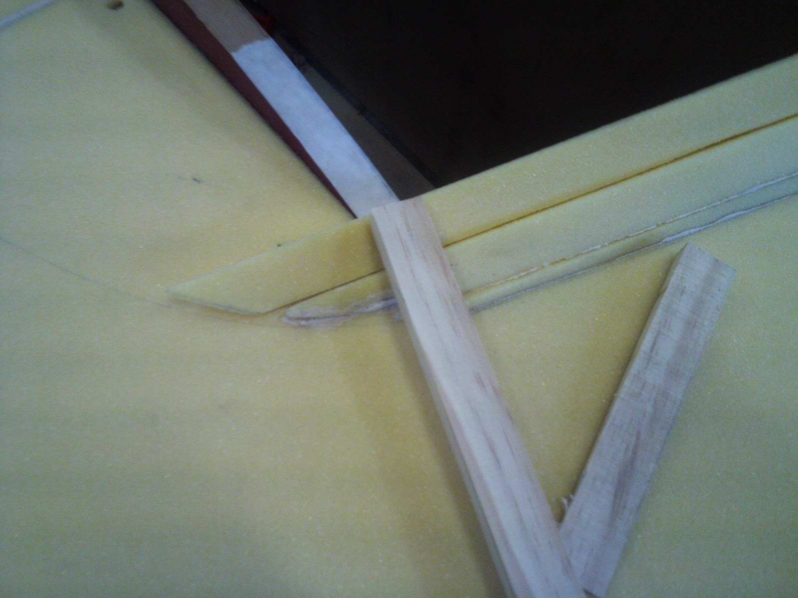
The foredeck pieces had to be fit in up tight to the blister.  James was in charge of getting this right.  He measured what the bevel was at each station and then transferring that to the foam.  It require a great deal of patience and time because the pieces needed to fit to the cabin top but also to each other and the foredeck has camber that the foam needs to bend around. 

We vacuumed the glass on the deck in order to achieve several different goals:  trying to wick out extra resin,  ensuring a smoother surface, getting an extremely tight fit and finish on the foam which will eliminate air pockets and therefore delamination.  When doing a vacuum there are several things that must be done in addition to the peel-ply and glass.  I will create another post that discusses this completely but what I want to mention here is that we needed to have room for the vacuum tape so the foam extended out past the deckline 50mm so this could be accomplished.


On the bulkhead that was attached there needed to be some work as well.  The mast would come in directly on top of it and the vang would come from the join on the cockpit sole and bulkhead.  There would also be a hatch the would be cut out so that a person could get inside the boat.  In order to support all the weight and compression load that would be put we installed some glass plate that is 15mm thick and at varying sizes at these locations.  Also a some carbon uni strips would be glassed in to give the boat the stiffness to support the load.  These strips would be carried all the way down the bulkhead to the hull and then dispersed out.


Because this part of the deck is what people will see most we had to hide all of the overlaps in the glass by rebating the foam.  We made some special blocks that had sandpaper exactly 50 wide and then rebated all of the spots that would have an overlap.


Another problem that we had was with the transom.  We had to think for discuss the many different options we had about attaching it.  We could either build the deck and the hull and then attach and then fit the transom, or attach the transom to one of the two halves. I will have another post later about the transom and all of its problems.

Foam Deck


We stared on the deck by making the cockpit sole. This is main area of the deck where you would stand/sit. The foam used for the entire deck we got extremely cheap, mainly because most of the foam had defects in it. These defects were not extremely damaging but we had to be careful when selecting the pieces that we were going to use. The cockpit sole pieces had little holes throughout, almost like it was perforated. Because we are going to be vacuum sealing the deck we needed to preglass the underside of the cockpit sole before it was put into situation. We built the cockpit sides in nearly the exact same fashion that we built the topsides on the deck, by using a scribe. None of the pieces that we used throughout the entire deck were ever big enough so one of the main problems that we had to solve was to figure out where we would put all of the joins in the different pieces and do this in the most economical way. After we glued down the cockpit side we started on the foredeck. This part was tricky because there were many different ways that we could work out how to put the foam down and we were running short on pieces of foam that we had left. We cut many different shapes out of some cardboard and moved them around on the deck many different times in order to find the best fit. After that the side deck just fit right in. I would say that putting the foam on the deck was very similar to strip planking the hull, only after we had the first planks down. The deck did not really require much analytical thinking and we were able to have the majority done in 4 days. The cabin top or blister was slightly tricky but not overly challenging. The shape required us to makes strips of foam that were tapered and beveled. The trickiest part of this was figuring out a way to hold the foam down in place without putting nails in the foam.


Creating the Deck Building Base


This boat is built in two main pieces that we fit everything else into and then attach.  I have already discussed the building of the main part of the hull and now it is time for the deck.  We went through and set up the temporary frames in the exact same way that we set up hull.  What was good about this time is that it took us maybe half as much time to do this because we had already learned how to do it, even though we had a bit of a problem.  Because many, many boats have been built on this floor and done so in a similar manner there was 'no more nails' glue still stuck on the floor that we were unable to scrape off.  We had to fit the building base down anyway and so there were uneven spots for when we used the theodolite.  About station 8 we had a problem.  Because we did not notice that the floor was higher on the port side we did not set the first frames up high enough.  So when we got further aft, station 8 to about 12, the port side had to be lowered down further than it could because the frame was resting on the building base.  (In case I neglected to mention this earlier, when we set up the frames we use a theodolite and a stick with a level line that is attached to a waterline on the boat.  We then use wooden wedges to raise the frames to match the two lines.)  So when we needed to lower the port side of the frames we had a bit of a problem.  We decided that instead of ripping up everything that we had done and redrawing everything and essentially loosing an entire day of work it would considerably easier to just trim the temporary frame on that side.  Two minutes later, we were on our way again.  It was a very simple solution to a problem that was quite serious at the time.

We also built one of the bulkheads into the deck temporary frames.  Station 7 has a bulkhead that takes all the weight from the mast.  This frame is built in to the deck because it was part of the deck as well as a main part of the structure, i.e. bulkheads, floors, girders.


Saturday, June 11, 2011

Glassing the Hull


There are several steps that we had to remember when we actually started glassing.  We had to get everything set out and ready for once we actually made the resin because it can become unworkable fairly quickly (something that was just seconds away from happening to us).  We had to first plan how we would lay the glass out and what kind of an overlap the different sheets would have.  After talking to the designer we learned that the overlap should be no less than 40mm but no more than 50mm, with 50mm being the ideal.  We decided to start in the middle of the boat and do the two sections around that and leave the bow for last because it would require the most patience and skill.  After we determined where the different sheets would lie we cut the peel-ply to the right length and started to mix the resin.  Peel-ply is special for a couple reasons: 1.  it keeps the job clean because we just tear it up when we are done  2.  it flattens out the job and wicks up the excess resin.  We used hand brushes, plastic spatulas and rollers to apply and spread out the resin.  One thing that we found hard to do was to keep the glass cloth down in the chine, where the foam and wood join was.  The resin would run down the topside and so the natural reaction is to squeegee it back up but that would pull the cloth from the join.  We had squeegee down from the topside and up the wood planking.  The bow was as predicted.  Because the shape was so tight and narrow and the difficulty in dealing with the glass cloth we had position the cloth and really struggle to get the lay that we wanted.  When we put down the peel-ply we just put two different sheets down because it doesnt really matter how it lies.